High Voltage RF Generator Photo Gallery
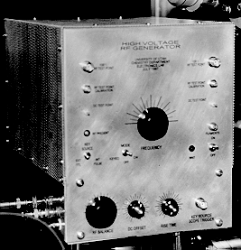
FRONT VIEW
The main frequency adjust knob is in the center. This adjusts the main frequency tuning capacitor. The knobs along the bottom are for the following: RF balance which is for fine adjustments to the RF amplitude on one output phase to help balance the amplitude of the RF output; a DC offset adjustment to adjust the slight DC voltage applied between the two output phases; a Rise Time adjustment for adjusting the rise time for the RF output when the keying option is selected; and a trigger output for triggering an oscilloscope to the keying signal, should on-off keying be selected.
A 100:1 attenuated copy of the RF output from each phase is available on the two front panel BNC connectors on the top left and right side. Below them is their associated calibration adjustment. And below that is a DC test point for measuring the DC voltage on each output phase.
Also on the front panel are various switches and lights for power and on-off keying.
DC power for the main high voltage plus the DC float voltage are see connected from the side connectors as well as the optional external TTL keying input.
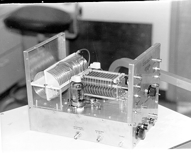
OPEN SIDE VIEW
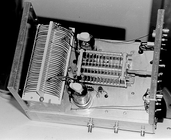
The majority of the RF components may be seen from this view. The main tuning capacitor is rated at 4 kV. The main tank coil is home made, wound on two plastic plates. The coil was first wound around a pipe to set the basic shape, then threaded through holes drilled and spaced in the plastic plates. The whole process went surprisingly smoothly and was far less expensive than purchasing coil stock. The location of the two vacuum tubes can be seen. The placement of the RF components is somewhat critical. All leads should be as short as possible to avoid stray capacity and inductance and to help with stability. The circuit is balanced with two tubes each in a sort of mirror image of each other and the component layout should reflect this balance. This helps keep stray capacity, inductance and losses somewhat symmetrical with the two output phases. The tubes should be mounted as close to the coil as possible and the leads from the plate of the tubes to the coil should be as short as possible.
The connections for the high voltage power supply, the DC float supply and the TTL keying are seen along the side. The coil and capacitor are insulated from the chassis by plastic mounting hardware. The tuning knob for the capacitor is connected to a plastic insulated shaft extender. There are very high voltages on the capacitor and coil.
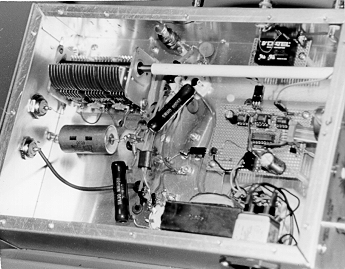
BOTTOM VIEW
The front of the RF generator is on the right. The keying circuit is on the circuit board with the integrated circuits. This circuit is not required if on-off keying is not required.
The black circuit on the top right part of the photo is a DC to DC converter to provide the differential DC voltage that can be applied BETWEEN the two output phases. The "common" output of this power supply is floating and is connected to the external float supply and is DC coupled to the output phases. This allows the output to have a DC bias equal to the DC float voltage and each phase to have a slight DC difference set by the DC to DC converter. You may not need this at all, or if you only need DC differenct potentials occasionally, you could use pair of batteries to supply the voltage.
The DC to DC converter is powered by the +5V supply which powers the keying circuit. If the keying circuit is not required, it may be easier to simply put a pair of batteries in place of the DC to DC converter, since there is no other need for the +5 V supply. An important consideration for the DC to DC converter is isolation voltage which is the maximum voltage it can stand from ground on the input side to the common on the output side. The voltage across the converter will be equal to the float voltage plus the DC high voltage. If the DC high voltage 600 V which is near the tubes maximum and the DC to DC converter isolation voltage is 700 volts, the float voltage can be only as high as 100 V. Using a battery in place of the DC to DC converter is a good option if very high float voltages are required.
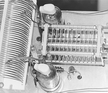
The variable capacitor near the top left of the photo is the RF balance adjust capacitor. RF imbalance is caused when one phase has more losses to ground than the other phase. This is one reason symmetry in the layout is important. The balance capacitor is in parallel with the coupling capacitor to one of the output phases and helps correct slight imbalances in stray losses in the circuit. The capacitor has only a small affect and larger adjustments may be made by adjusting the taps on the coil and by changing the values of fixed coupling capacitors. This capacitor is totally isolated from ground and uses a long plastic shaft extender.
Also, can be seen in the photo is the filament transformer which also provides power for the 5Vdc supply. The tube sockets are somewhat hidden, but it can be seen that the leads for all RF paths are very short. The power resistors connected to the two tube sockets are for the screen. The high voltage DC input is coupled to the RF choke seen near the top center of the photo.
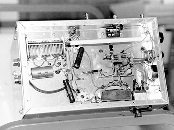
ANOTHER BOTTOM VIEW
This is another view of the bottom from a slightly different angle. AC power comes from the side through an RFI filter. The front panel variable resistors can be seen as well as a slightly better view of one of the tube sockets. Most of the wiring on the front half of the picture is related to the keying circuit and could be eliminated if on-off keying is not required.
TOP VIEW
Notice the symmetry and close placement of the tubes to the coil. The plate leads are kept short. The coil is held in place with screws on the ends holding it to a plastic form. On the center of the coil is soldered the metal part of a female banana plug. On the chassis is mounted, on a plastic standoff, the metal part of a male banana jack. The coil is put in place by pushing the connectors together and held down with a screw on each side of the coil form. The remaining taps on the coil are made with small alligator clips which have been formed to not short out windings. Adjusting the taps adjusts the frequency range the capacitor can tune and helps adjust the RF balance.
TOP CLOSEUP
This is a close-up of the previous photo sowing a bit more detail of the coil and taps. In addition to the center tap which is made with the modified banana connector, there are 4 taps, two symmetrical on each side of the center tap. The outer connections are to the plates of the tube and the tuning capacitor and the inner taps are two or three turns in from the outer taps and connect to the grids of the opposite tube. The plate leads should be as short as possible, but long enough to allow for adjusting, the grid leads can be much longer. In this case, they go down through an insulator to the inside of the chassis and cross to the opposite tubes.
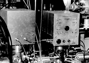
A PAIR IN ACTION
This shows two RF generator in use. In this photo, you can see the rear panel. In some of our applications we found it difficult to get to the rear panel when the generator was hooked up, so we put all controls on the front or side. The connection to the output is a UHF connector (PL-259), however the center pin accepts a standard banana jack. If coax is used to connect to the load, the extra capacity of the coax must be considered. Using coax to connect to the load electrically is like adding an extra capacitor across the load. This will reduce the frequency. Also, the coax should be able to stand the output voltage. Since this circuit is not an amplifier delivering power to a match load, the impedance of the coax is not important. In practice, RG-8 type coax that is not much longer than about a meter should work fine.
Links to:
RF section schematics and description